Ultra Clean Power Supply
Apr 24, 22Files
Notes
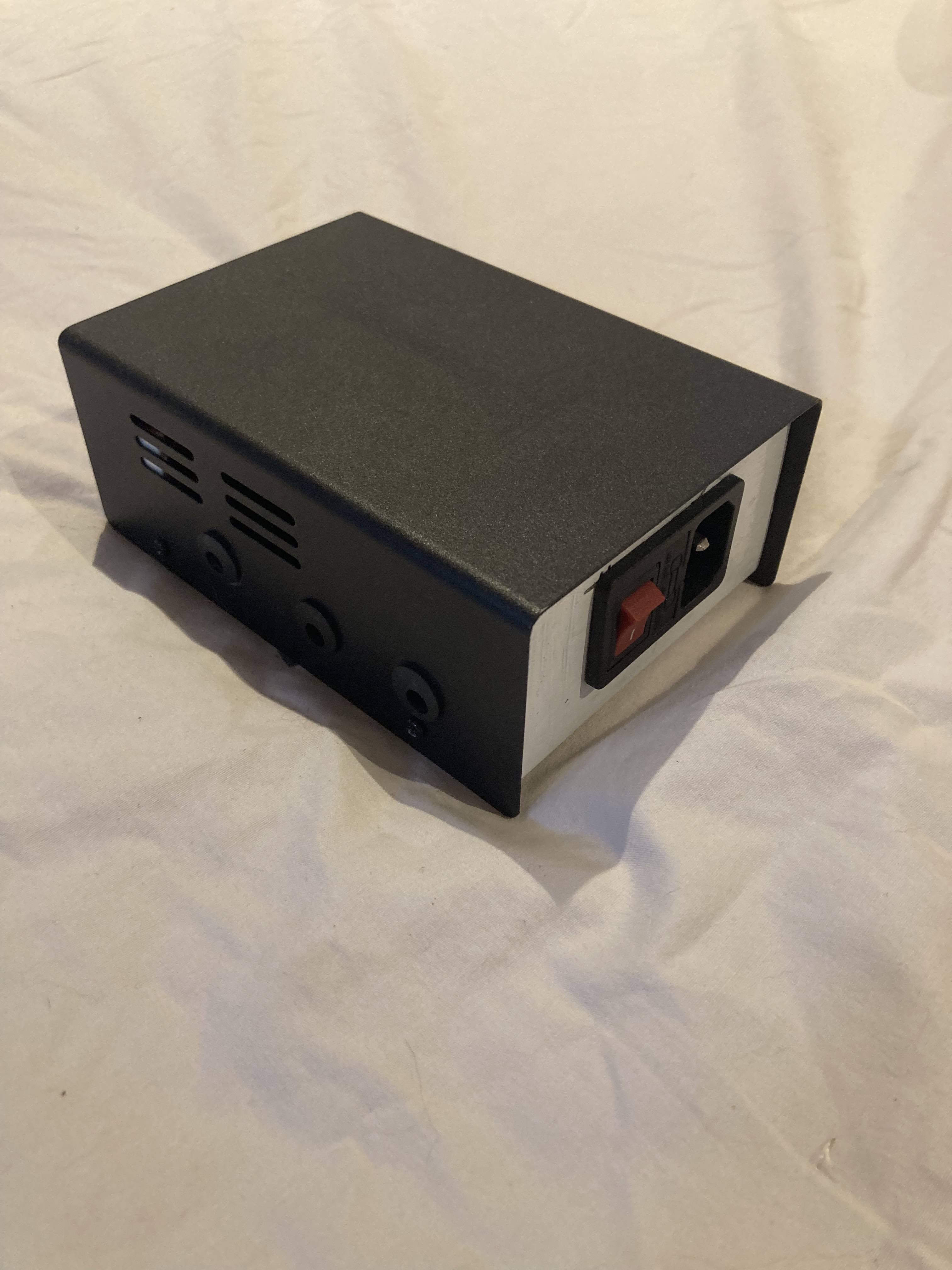
I made this power supply for my guitar pedals, to avoid using batteries. It was actually the simplest project I’ve done. The only difficult part was deducing what transformer to actually use, what fuse type to use, and how to ground the electrical appliance, given it’s using 230V AC, as this was not given on the schematic.
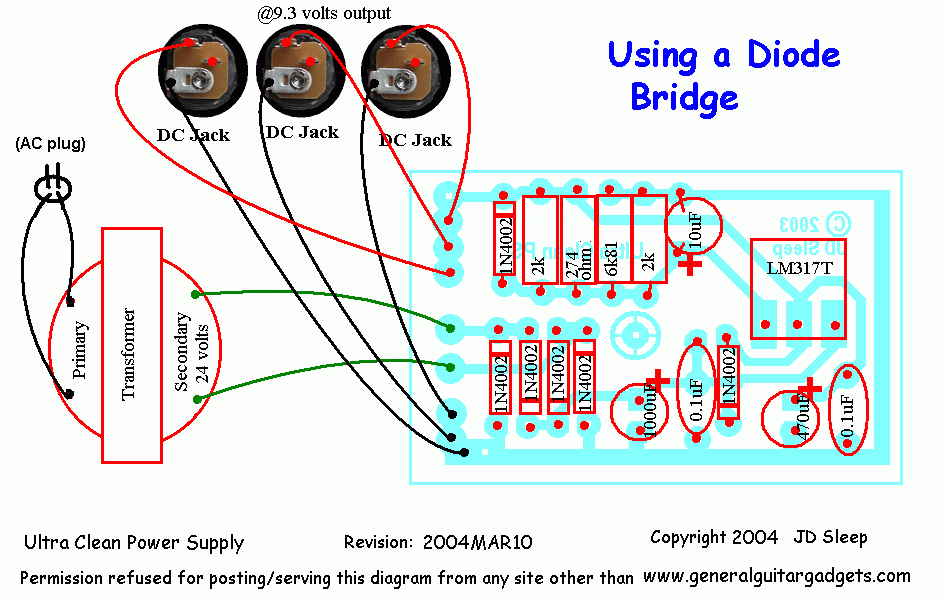
Here are the notes I wrote at the time. Most of these notes came from the diystompboxes forum, in particular the very smart member RG.
What Transformer To Use
- In the end, use a 12Vac 1A transformer, which is almost as common as dirt in the trade, will be just about perfect for your 9.35V 0.5A output in that circuit.
How many pedals could I run off this power supply?
-
The LM317 will supply 1 amp if fitted with a good heatsink. Thats 1000mA. Add up the total current draw of all your pedals. It will only do about 100mA or less without a heatsink, depending on the input voltage from the power transformer.
-
Current draw: At most pedals usually have 100mA draw most seem to have 10mA or less
For metal enclosures / grounding
Don’t be afraid: just connect the ground pin of the power cord securely to the metal box. Use a screw that doesn’t attach to anything else, and give it a lock washer and a ring terminal. Solder a (green) wire from the ring terminal to the ground pin of the AC cord connector.
As to construction: I would NOT put a supply designed to provide up to one amp (which the Ultra-Clean can) in a plastic case of any sort. My caution on this point stems from some failure-mode experiments that I did when designing the Small Wart; if the output is shorted, the regulator chip will protect itself. But that will not stop the transformer from overheating and possibly causing a fire hazard. Even a fuse on the transformer primary might not blow. If you build the Ultra-Clean, build in metal.
After readin the above, I chose this enclosure which works fine for a transformer of size 50mm x 85mm x 40mm:
https://www.jaycar.com.au/metal-case-150-x-61-x-102mm/p/HB5442
Fuse considerations
Fuse the AC power entrance. This is a bare minimum. Use a slow-blow/time delay fuse of a rating that will let it start reliably. This must be larger than you think, because the size of the inrush current depends on exactly where in the AC power cycle the power was turned off last time and where it was turned on this time. I once had a variac that was perfectly normal, but about one time in ten blew a 20A wall-socket breaker. I found 200A peaks on some power-ons with this. It was all dependent on how much it took to charge up the core and any filter caps it eventually powered. This fuse is a critical part of electrical and fire safety. Pick the value of the fuse by picking the smallest size that will both start reliably on input surges and stay on for maximum-normal use. This is why on the AC input, you put a fuse that will withstand the full operating current, or a little bit more, and make it a slow blow. Slow blow fuses will withstand large pulses for a short time. This is good, because transformers and motors can easily pull 10-20 times their normal max operating current for a half-cycle of the incoming AC power. The time delay lets it get started without choosing a huge fuse to start, then melting down on normal operation without popping the big fuse.
You can calculate crudely what the max currents will be. Your trannies are rated for 12V/200ma outputs. Actually, they’re probably 14-15Vac open circuit, but 200ma RMS outputs. So they put out about 2.8W each at full load. On the primary, that’s about 2.8W/120V = 23ma. Actually, it will be greater, because small trannies usually have poorer primary inductances. Call it 30ma each. Five of them are about 150ma. That will be the highest combined primary load you want to see. Fuse the primary at the nearest fuse you can get bigger than 150ma time delay/ slow blow rated.
Each output is feeding a full wave bridge rectifier. One of the quirks of full wave bridges is that the RMS/heating current they pull from secondaries is about 1.6 to 1.8 times the DC current that goes out of the filter cap. So if your transformers are rated at 100ma per secondary, and you full wave rectify them, then you can pull out something like 100ma/1.8 = 56ma per secondary on a continuous basis. Notice that the secondary IS conducting 100ma, but you only get 56ma of usable DC from it. So a 100ma fuse would protect the secondary. This may or may not need to be slow blow. The first cycle of AC coming in tries to charge the completely empty first filter cap, so it looks like a short circuit for a half-cycle or two.
Why you need a slow blow instead of fast for the primary side
Someone wrote…
I’m surprised no one pointed this out, but you should not use a slow blow fuse. If that fuse needs to blow, you want it to blow fast. There are a limited number of uses for slow blow fuses, this not being one of them.
To which RG answered:
Actually, it is one of them. One of those limited uses for slow blow fuses is on the primary of a power transformer. At power, the transformer core must be magnetized, and depending on the remanent magnetism in the core and the phase in the AC line at which it’s connected, the power surge to magnetize the core, including any saturation from the phase and remanence can be large. In addition, at power on, the filter caps are at zero volts, so they instantaneously look like a short circuit on the secondaries.
The question is generally moot with small transformers which have relatively high winding resistance, but an AC power safety fuse is one of the places you want a slow blow in general.
Fuses in general, even “fast blow” types, are not in general fast enough to clear in time to protect semiconductors which are not otherwise protected from overcurrents. It’s a truism of power amplifier design that you cannot protect a power transistor with a fuse; the transistor almost always gives its life to save the fuse.
AC Power Socket Wiring
Photos